
An Australian Perspective
Part 3: Deep Technical Dive - DC Fault Protection, Reliability, and Generator Integration
Side Note 1: The Peril of Breaking DC
The single most dangerous engineering nuance in an 800V DC system is not the voltage itself - it is the lack of a natural zero-crossing. This is where AC and DC fundamentally diverge, and it has profound implications for circuit protection.
In an AC circuit (at 50 Hz), the current reverses direction and drops to zero 100 times every second. At those zero-crossings, the arc created when contacts part is naturally extinguished. The arc plasma dissipates, and the circuit is broken. This natural "assist" is why AC switchgear is comparatively straightforward (though still hazardous).
800V DC offers no such mercy. The current flows continuously in one direction. When a contact opens under load, an arc strikes and becomes a sustained plasma torch - there is no natural zero to quench it. The arc will persist indefinitely unless the switchgear actively forces it out. This requires:
Magnetic blow-out coils that use electromagnetic fields to deflect and stretch the arc into an arc chute.
Arc chutes with de-ionising plates that split and cool the arc to force extinction.
Much faster contact separation speeds to increase the arc gap before the energy builds.
Significantly larger air gaps - an 800 VDC arc can sustain itself across a gap that would easily extinguish an AC arc at the same RMS voltage. Australian standards (AS/NZS 3000) do not yet have definitive DC clearance tables for this regime, forcing designers to fall back on conservative IEC 60664-1 calculations that often specify double the clearance distance for DC compared to AC.
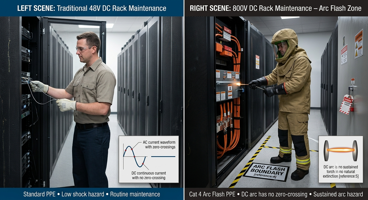
The result is bulkier, more expensive switchgear, and far more stringent maintenance protocols. Arc-flash incident energy for DC faults can be higher and more sustained, meaning personal protective equipment (PPE) requirements in Australian facilities may need to exceed standard AC ratings. Fault interruption in DC is not a matter of waiting for the wave to cross zero - it is a matter of ripping the arc apart by force before the ionised plasma vaporises the switchgear itself.
Side Note 2: Uptime Tier III/IV Considerations
The 800 VDC transition is not simply a voltage upgrade - it must be engineered to meet the stringent reliability requirements of Tier III (concurrently maintainable) and Tier IV (fault tolerant) data centres. This introduces a fundamental tension: the architecture that maximises efficiency is not always the architecture that maximises resilience.
Tier III: Concurrent Maintainability
Tier III requires that any component can be maintained or replaced without disrupting IT operations. For 800 VDC systems, this means:
Dual power feeds to every IT rack: All computer hardware must have dual power inputs to enable concurrent maintainability. In the 800V DC context, this translates to dual 800V DC bus feeds from independent switchgear paths.
N+1 redundancy at every layer: Transformers, switchgear, busducts, and power shelves must all be N+1 configurable. This is where the sidecar architecture proves its worth - modular power shelves with hot-swappable rectifier modules allow individual units to be replaced without taking the entire rack offline.
Distributed redundancy architectures: The industry has developed three primary redundancy frameworks for 800 VDC systems:
| Architecture | Description | Load Efficiency | Best For |
|---|---|---|---|
| 2N | Two independent, redundant power systems operating in parallel. Any single failure is seamlessly absorbed by the other path. | ≤50% | Tier IV fault-tolerant requirements |
| DR (Distributed Redundancy) |
Load is split across N groups (N≥3), each with two independent feeds. Any single feeder failure does not interrupt power. | ≤66% | Tier III with higher utilisation |
| RR (Reserve Redundancy) |
Multiple primary systems share one or two common backup systems. Loads can be rapidly switched to reserves upon failure. | Up to ~90% | Hyperscale AI factories prioritising efficiency |
DR and RR architectures are emerging as the pragmatic choices for AI factories, where the sheer scale of power infrastructure makes 2N's 50% utilisation ceiling economically prohibitive.
Tier IV: Fault Tolerance
Tier IV demands that no single equipment failure or distribution path interruption impacts operations. This is N+N (fully redundant, independent, and physically separated) redundancy, not merely N+1.
For 800 VDC systems, Tier IV compliance requires:
Physically separated power paths: Two completely independent 800V DC distribution paths—from separate SSTs, through separate switchgear line-ups, along separate busduct routes, to separate sidecar power shelves—terminating at dual-input IT racks. No single point of failure anywhere in the chain.
Independent backup systems: BESS and supercapacitor banks must be duplicated across both power paths, with no shared components that could create a common-mode failure.
Automatic fault isolation: Protection systems must detect and isolate faults without manual intervention, and do so faster than the fault can propagate. This is where solid-state circuit breakers with microsecond-class response become essential - mechanical breakers simply cannot react fast enough.
Side Note 3: The Generator Challenge
The Uptime Institute is unequivocal: on‑site power production systems (e.g., engine generators) are considered the primary power source for the data centre. The local utility is merely an economic alternative. Disruptions to utility power are not considered a failure, but rather "an expected operational condition for which the site must be prepared." Accordingly, on‑site generators must automatically start and assume load upon loss of utility. For Tier III and Tier IV sites, generators shall not have a limitation on consecutive hours of operation when loaded to full demand.
This presents a fundamental question: how does a "grid‑to‑chip" 800V DC architecture—which eliminates multiple AC‑DC conversion stages - integrate with on‑site generators that natively produce AC power?
The Problem: Generators Produce AC, Racks Want DC
Traditional generator integration is straightforward: generators produce 415V AC, which feeds the existing AC switchgear and UPS systems. In an 800 VDC architecture, the IT load sits on an 800 VDC bus. Simply connecting a 415 VAC generator to that bus is not possible - you need a rectifier stage to convert the generator's AC output to 800 VDC.
The challenge is that during a utility outage, every watt of IT load must be supplied by the generator, converted to DC, and distributed via the 800 VDC bus. This means:
The generator must be sized to handle the full IT load plus the losses of the AC‑DC conversion stage
The rectifier must be rated for the full generator output
The transfer from utility‑fed SST to generator‑fed rectifier must be seamless
The Solution: Multi‑Port SSTs with Generator Integration
The answer lies in the multi‑port solid‑state transformer (SST) . Unlike a traditional transformer with a single input and output, modern SST platforms such as DG Matrix's Interport™ are designed with multiple ports that can route power in real time across AC and DC sources, loads, and storage at multiple voltage levels.
In practice, this means:
Normal operation: The SST takes 11 kV or 22 kVAC from the utility grid and converts it directly to 800 VDC for the IT load.
Utility failure: The SST seamlessly switches to a second AC input port connected to the on‑site generator. The SST's internal rectifier converts the generator's 415V AC output to 800 VDC, maintaining the DC bus.
No additional conversion stages: The same SST that handles utility power also handles generator power - no separate rectifier cabinets, no additional switchgear, no double conversion losses.
This is the fundamental architectural advantage: the SST becomes the universal interface between any AC source (utility or generator) and the 800 VDC bus.
The Microturbine Alternative: Direct 800 VDC Generation
An emerging alternative is on‑site generation that natively produces 800 VDC, eliminating the need for AC‑DC conversion altogether.
Capstone Green Energy and Microgrids 4 AI have announced an 800 VDC natural gas microturbine designed to directly interface with NVIDIA's Kyber and Rubin Ultra platforms. The system eliminates multiple AC/DC conversion stages, reduces copper mass by up to 45%, and improves overall power efficiency by as much as 5% compared to legacy 54V systems.
Each "AI Power Block" delivers power, liquid cooling, and compute as a unified, rapidly deployable system that can scale from edge deployments under 20 MW to AI giga‑campuses exceeding 1 GW. This approach effectively removes the utility grid from the equation entirely - the data centre becomes a self‑contained DC microgrid.
The BESS + Supercapacitor Buffer
Even with generator integration, there is a critical gap: generators take seconds to start and synchronise. In that window, the IT load must be supported by stored energy.
The 800V DC architecture addresses this through parallel BESS and supercapacitors tapped directly onto the 800V DC bus:
Supercapacitors respond in microseconds to milliseconds, bridging the gap between utility failure and generator start.
BESS provides 1 MW for 3 minutes or 1.2 MW for 90 seconds per rack, sustaining the load until the generator stabilises.
The SST routes power in real time across AC and DC sources, loads, and storage, absorbing load transients and supporting fault ride‑through.
Crucially, this is a parallel architecture - the BESS and supercapacitors float on the DC bus, only discharging when needed. There is no series double‑conversion loss, unlike traditional UPS systems.
The Shifting Role of Generators
Interestingly, the role of on‑site generators is itself evolving. Industry observers note that traditional generator backup coverage has dropped to between 15% and 40% on new projects. Hyperscale operators are increasingly using software to shift computing workloads geographically during grid disturbances, reducing the need for complete physical redundancy on‑site.
However, for Tier III/IV certified facilities, generators remain non‑negotiable. The 800 VDC architecture does not eliminate the need for generators - it re‑engineers how they integrate:
| Aspect | Traditional AC Architecture | 800V DC Hybrid Architecture |
|---|---|---|
| Generator output | 415V AC | 415V AC (or direct 800V DC via microturbine) |
| Generator‑to‑load path | Generator → AC switchgear → UPS → PDU → rack PSU | Generator → SST (AC‑DC rectification) → 800V DC bus → sidecar → rack |
| Conversion stages on generator | 3+ stages (AC‑DC‑AC‑DC) | 1 stage (AC‑DC via SST) |
| Backup bridging | UPS batteries (series, double conversion) | BESS + supercapacitors (parallel, no double conversion) |
| Transfer time | UPS carries load during transfer | Supercapacitors respond in microseconds |
Tier III/IV Compliance
For operators targeting Tier III or Tier IV certification, the 800 VDC architecture must meet the same rigorous generator requirements:
Tier III: N+1 generators with a minimum of 12 hours of fuel
Tier IV: 2N or 2N+1 generators with a 96‑hour fuel reserve
No runtime limitations: Generators must support continuous operation at full load
Concurrent maintainability: Generator systems must be maintainable without disrupting IT operations
Engineering Challenges Summary
Safety: At 800 VDC, we are dealing with potentially lethal power levels. Arc‑flash hazards are a very real practical issue—approaching an energised rack beyond the arc‑flash boundary will require arc‑flash suits and enhanced protection measures. Facilities must update electrical safety procedures, conduct proper NFPA 70E (or local AS/NZS 3000‑equivalent) hazard analyses, and train staff on DC‑specific lockout procedures.
Standards Fragmentation: The standards landscape remains fractured, with organisations making engineering decisions under conditions of regulatory uncertainty. Australian operators must navigate both international (IEC, UL) and local (AS/NZS) frameworks, many of which are still being drafted for 800 VDC systems.
Protection Circuitry: Higher‑voltage DC distribution increases demands on monitoring and protection circuitry. Every disturbance or transient condition carries more stored energy, with components operating closer to their absolute limits. Solutions such as Delta's e‑Fuse Module with SiC switch technology achieving fault cutoff in less than 3 μs are critical enablers.
High‑Ratio Conversion: Stepping 800 VDC down to the sub‑1V levels required by modern processors demands 64:1 conversion ratios and beyond. This pushes the limits of magnetics, semiconductor switching, and thermal management.
Grid Interconnection: As AEMC and AEMO tighten rules for large loads, 800 VDC facilities must include grid‑friendly features such as reactive power support, harmonic filtering, and fast‑ramp capabilities to avoid destabilising the local network.
Conclusion: Engineering Necessity, Not Hype
800V DC in the AI data centre is not marketing hype. It is a physics‑driven engineering response to an unprecedented density problem.
The traditional 48V architecture was never designed for megawatt‑scale racks. The copper, the losses, the space consumption—these are not negotiable constraints. They are fundamental physical limits.
But the "grid‑to‑chip" narrative needs correction. The reality is a hybrid architecture: 800VDC for high‑efficiency IT load delivery, whilst AC infrastructure continues to serve mechanical loads and facility services. Switchgear, busducts, and BESS form the new physical infrastructure layer- each demanding engineering re‑thinking.
For hyperscalers building gigawatt AI factories, 800 VDC is the only viable path forward. For the Australian market, with AEMC's new rules and NVIDIA's 2027 deployment timeline as dual catalysts, the adoption curve will be measured in years, not quarters. But the trajectory is clear: power infrastructure, once an afterthought, is becoming the primary factor that dictates the scale, location, and feasibility of new AI deployments.
SemiAnalysis predicts that by 2030, roughly 39 GW of incremental AI data centre capacity will adopt 800V DC architecture. This scale of infrastructure transition demands far more than a voltage uplift - it demands a fundamental re‑engineering of how we deliver power to compute.
The 800V DC transition is not a marketing fad. It is the inevitable consequence of physics. Australian engineers, regulators, and operators must prepare now, because the megawatt‑scale rack is not a future hypothetical - it is already being designed into tender documents across Sydney and Melbourne.
The question is no longer whether 800 VDC will arrive, but whether Australia's supply chain, certification bodies, and grid operators will be ready when it does.
[End of Part 3]