
An Australian Perspective
Part 1: The Density Imperative and Architectural Shift
The Density Crisis
For decades, data centre power distribution followed a predictable trajectory. Server racks consumed tens of kilowatts, 48VDC distribution sufficed, and power infrastructure was a secondary consideration - an afterthought in facility design. Those days are over.
The rise of generative AI has shattered this paradigm. The leap from NVIDIA Hopper to Blackwell illustrates the magnitude: individual GPU TDP increased by 75%, but the NVLink domain's expansion to a 72-GPU system drove a 3.4x increase in rack power density - delivering a 50× performance gain while pushing racks from tens of kilowatts well past 100 kW. Today, AI racks already operate at 140 kW, with 240 kW close behind and 600 kW racks - even megawatt-class scenarios - on the horizon.
This is not a gradual trend. This is a discontinuity.
The Physics Problem with 48V
The traditional 48V/54V in-rack distribution architecture was designed for kilowatt-scale racks. At 140 kW and above, the physics become intractable.
Consider the arithmetic: delivering 1 MW at 48V requires over 20,000 amperes. The copper cross-section alone becomes physically unmanageable - cabling would consume rack volume that must instead house GPUs. For a typical 1 MW feed, the copper mass approaches 180 kilograms. At 800V, the same 1 MW requires only 1,250 amperes - a 16× reduction in current. Copper mass drops to roughly 18 kilograms, a reduction of 90%. Enverus Intelligence Research estimates that 800V DC distribution can lower electrical capital expenditure by 13%, lift end‑to‑end facility efficiency from 79.8% to 93.8% (a 14% point gain), and cut copper usage per megawatt by up to 60%.
The implications cascade through the entire power chain:
Copper reduction: from ~180 kg to ~18 kg for the same load
I²R losses: resistive losses reduce by a factor of 256 (since P = I²R)
End‑to‑end efficiency gains: up to 5% improvement
Cable bulk reduction: eliminating the physical congestion that chokes rack density
NVIDIA's technical blog frames it directly: "Delivering this level of power at traditional low voltages, like 54 VDC, is physically and economically impractical."
The Synchronous Workload Challenge
There is a second, less obvious driver: volatility.
Traditional data centres run thousands of uncorrelated tasks, creating a relatively smooth aggregate power profile. An AI factory is fundamentally different. When training a large language model, thousands of GPUs execute cycles of intense computation followed by periods of data exchange in near‑perfect unison. This creates facility‑wide power swings that can switch from near‑zero to hundreds of megawatts and back again multiple times per second.
These load swings ripple upstream toward the grid and downstream into the silicon. The 800V DC architecture, paired with multi‑timescale energy storage, provides the foundation to manage this volatility - smoothing peak loads, providing second‑level backup, and enabling grid‑friendly operation.
The Architecture: Not Quite "Grid‑to‑Chip"
Industry marketing often touts a "grid‑to‑chip" pure‑DC path, but the engineering reality is more nuanced. Mechanical loads and general facility services still require AC power.
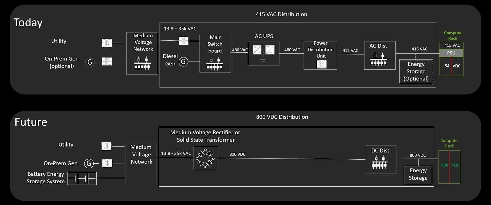
‘Grid-to-chip” 800 VDC power distribution in next-generation AI factories (Source: Nvidia)
Cooling plant is the largest AC consumer. Take Delta's 2.4 MW in‑row liquid‑cooled CDU showcased at NVIDIA GTC - whilst its pumps can be powered from 800V DC, most existing and near‑term cooling equipment (3 MW CDUs, fans, dry coolers, chillers) remains AC‑fed. Lighting, security systems, building management, fire suppression - all are AC loads. Thus, 800 VDC does not replace AC distribution; it runs alongside it.
Schneider Electric's "sidecar" approach acknowledges this reality: move the AC‑to‑800 VDC conversion out of the IT rack and into a dedicated power cabinet or upstream location. This allows operators to deploy 800V‑ready compute without converting the entire facility overnight. In a typical large data centre, dozens to hundreds of multi‑megawatt AC UPSs already exist - they will not disappear.
The emerging architecture therefore is a hybrid:
Medium‑voltage AC (e.g. 11 kV or 22 kV in Australia) → 800 VDC via solid‑state transformers (SSTs)
800 VDC distributed via DC busways to IT racks
800 VDC → 12V/48V via high‑ratio LLC converters at the rack or node level
12V/48V → processor core voltage (sub‑1V)
Separate AC paths continue to feed cooling, lighting, and facility services
Topology Comparison: 800 VDC Hybrid vs. Traditional
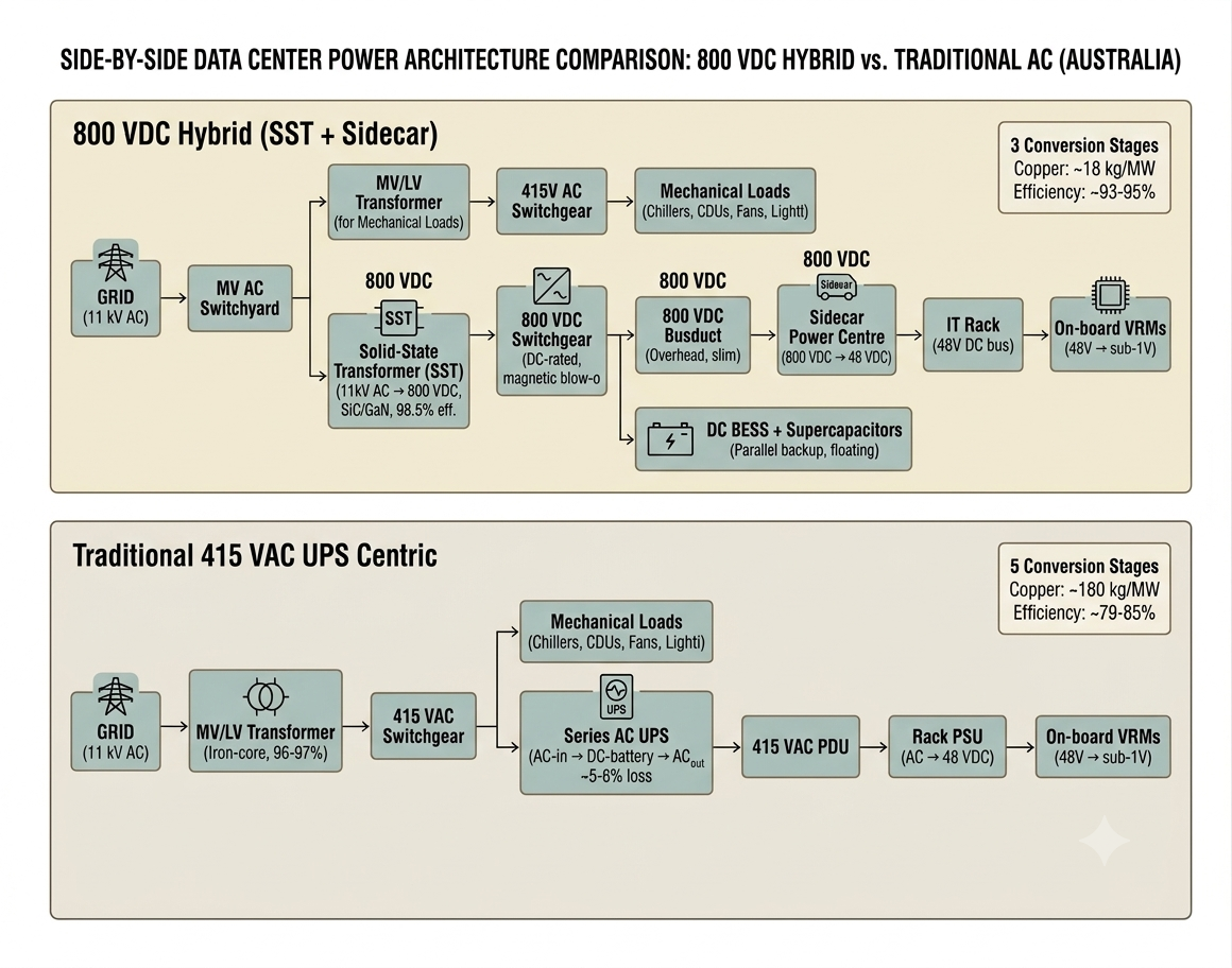
800 VDC Hybrid Topology (SST + Sidecar): This is the emerging architecture being deployed in AI factories globally, with Australian pilots already underway.
Traditional Topology (415V AC UPS‑Centric): This is the legacy architecture still deployed in 95%+ of existing Australian data centres.
Crucial takeaway: Cooling and facility services remain on the parallel AC path. The 800V DC path is dedicated exclusively to IT load. This is not a replacement of the whole facility - it is a parallel high‑efficiency expressway for compute power, while the AC "local road" continues serving everything else.
Architectural Comparison Table
| Attribute | Traditional 415V AC UPS | 800 VDC Hybrid (SST + Sidecar) |
|---|---|---|
| Primary Distribution Voltage | 415 VAC (3‑phase) | 800 VDC |
| IT Power Conversion Stages | 5 stages (AC→AC→AC‑DC‑AC→AC→DC→DC) | 3 stages (AC→DC→DC→DC) |
| End‑to‑End IT Efficiency | ~79–85% (typical operating point) | ~93–95% (demonstrated by Delta/Enverus) |
| Copper Mass per 1 MW Feed | ~180 kg (for 48V final distribution) | ~18 kg (for 800V busduct) |
| Transformer Technology | Line‑frequency iron‑core (96–97% eff.) | Solid‑State (SiC/GaN, 98.5% eff., 50% smaller) |
| Backup / UPS Strategy | Series AC UPS (AC‑in, battery DC, AC‑out). Double conversion losses (~5–6%) inherent. | Parallel DC BESS + Supercaps tapped directly onto 800V DC bus. No double conversion; backup is always "present" on the bus. |
| Switchgear Complexity | Standard AC switchgear. Natural zero‑crossing at 50 Hz aids arc extinction. | DC‑rated switchgear required. No zero‑crossing; relies on magnetic blow‑out coils, arc chutes, and larger clearances. Bulkier and more expensive. |
| Protection / Fault Interruption | Relatively straightforward. AC breakers trip at zero‑crossing. | High‑stakes. Fault current is continuous DC. Requires µs‑response e‑fuses (e.g., Delta's <3 µs SiC e‑Fuse) and active arc‑forcing mechanisms. |
| Cooling & Mechanical Loads | Fed from same 415V AC bus (separate PDUs). | Fed from parallel AC path (MV/LV transformer). Remains entirely separate from DC IT bus. |
| Busbar / Distribution Medium | Copper cables or AC busway (heavy, bulky). | High‑efficiency DC busducts (overhead, lighter, reduced congestion). Requires continuous microsecond‑response monitoring. |
| Footprint (per MW IT) | High: large UPS rooms, massive transformers, thick cable trays. | Compact: SST replaces room‑sized transformer; sidecar replaces bulky UPS; cabling volume shrinks. Recovers 8–16 RU per rack. |
| Rack Density Ceiling | Practically limited to ~60–80 kW/rack due to cable bulk and 48V distribution losses. | Enables 140 kW – 1 MW+ per rack. Designed for NVIDIA Kyber (576 GPUs) and beyond. |
| Grid Interaction (AEMC/AEMO) | Relatively passive load (continuous draw, moderate harmonics). | Requires grid‑forming / grid‑friendly features: reactive support, harmonic filtering, fast‑ramp capabilities to satisfy new AEMC draft rules for large inverter‑based loads. |
| Safety & PPE | Standard arc‑flash suits for AC (typically Cat 2–3). | Enhanced DC arc‑flash hazard. Sustained arcs require Cat 4 PPE, DC‑specific lockout/tagout, and adherence to updated AS/NZS 3000 & IEC 60664‑1 clearance rules (double the gap for DC). |
Why the Backup Strategy Fundamentally Changes
In the traditional topology, the UPS sits in series with the load. Every electron destined for the servers must pass through the UPS rectifier and inverter - even when mains is healthy. This incurs a ~5–6% permanent efficiency penalty.
In the 800 VDC topology, the BESS and supercapacitors sit in parallel on the DC bus. The SST feeds the bus directly. The batteries float on the bus, only discharging when the SST droops or fails. There is no double‑conversion loss during normal operation. When a load transient hits (a synchronous AI training step), the supercapacitors respond in microseconds, the BESS picks up in milliseconds, and the SST/rectifiers ramp to match - all without a single AC‑to‑DC‑to‑AC round‑trip.
[End of Part 1]
Continue to Part 2 for enabling technologies, vendor offerings, and the equipment ecosystem.